Trigger Blocks
Ndigo5G-10 record analog waveforms using zero suppression.
Whenever a relevant waveform is detected, data is written to an internal
FIFO memory.
Each ADC channel has one trigger block determining whether
data is written to the FIFO. The trigger blocks are configured
using ndigo_configuration::trigger_block.
Each trigger block consists of two independent units that check the incoming raw data stream for trigger conditions (Figure 10). The triggers of each trigger block can be configured to use level triggering (trigger if the signal level is above or below a threshold) or edge triggering (trigger if the signal level crosses-over a set threshold).
Level or edge triggering is configured using ndigo_trigger::edge.
The recording window can be configured using
ndigo_trigger_block::precursor and
ndigo_trigger_block::length, as highlighted in
Figure 11 and Figure 12.
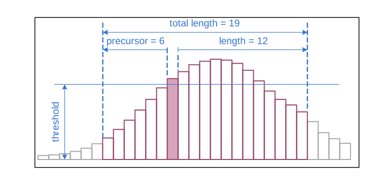
Figure 11 Parameters for edge triggering.
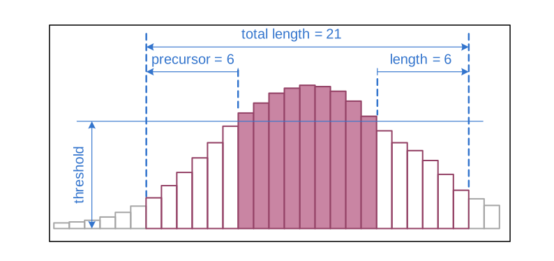
Figure 12 Parameters for level triggering.
When using edge triggering, all packets have the same length of precursor + length + 1 cycles of 3.2 ns.
For level triggering, packet length is data dependent.
Note that triggering is not accurate to sample. For each 3.2 ns clock cycle, it is determined whether for any sample during that clock cycle a trigger condition is met. That clock cycle is then selected as the trigger point. As a result, the trigger sample can be anywhere within a range of up to 16 samples depending on the ADC mode, as highlighted in the following figures.
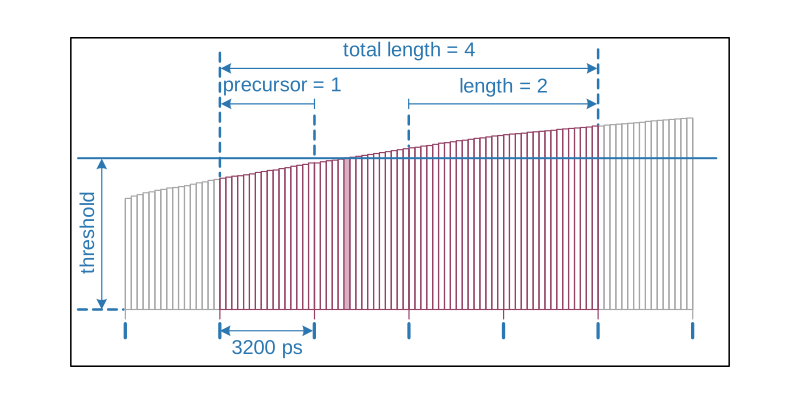
Figure 13 Triggering in 1-channel mode at 16 samples per clock cycle.
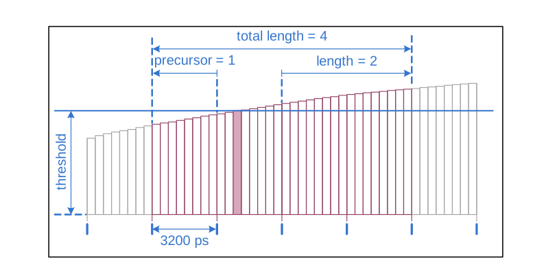
Figure 14 Triggering in 2-channel mode at 8 samples per clock cycle.
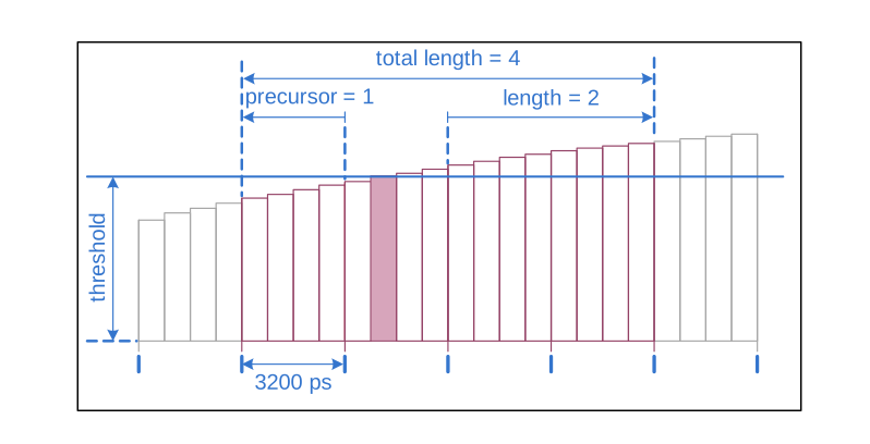
Figure 15 Triggering in 4-channel mode at 4 samples per clock cycle.
If re-triggering is active, the current trigger window is extended if a trigger event is detected inside the window.
A trigger block can use several input sources:
the 8 trigger decision units of all four ADC channels (Figure 16)
the GATE input (Figure 17)
the Trigger or TDC input (Figure 17)
a function trigger providing random or periodic triggering (Auto Trigger Function Generator)
triggers originating from other cards connected with the sync cable or from the Ndigo Extension card (BUS0, BUS1, BUS2, BUS3) (Figure 18)
A second set of trigger units with names ending in
PEfor the digital inputs Trigger, GATE, BUS0, BUS1, BUS2, and BUS3, configured for positive edge triggering. Together with the regular trigger units on these inputs, both edges of a pulse can be used in the trigger logic. However, this set of triggers is not available as inputs for the gating blocks.
Trigger inputs from the above sources can be concatenated using a logical
“OR” (see Figure 19) by
setting the appropriate bits in trigger_blocks::sources bitmask.
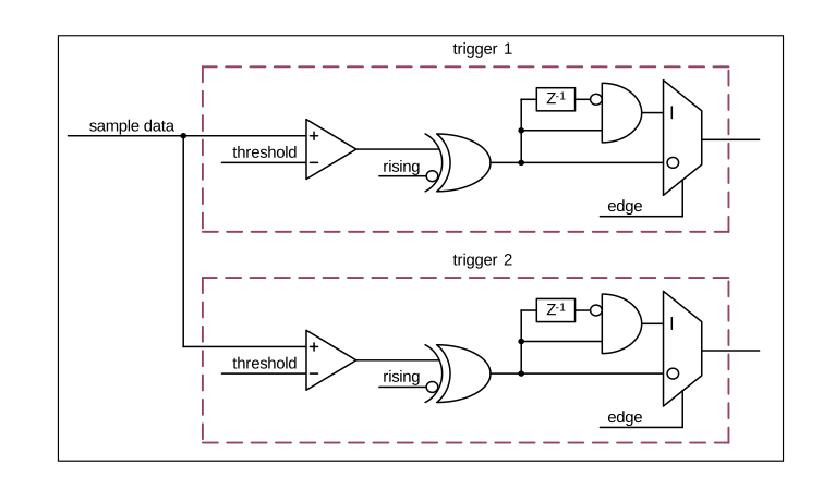
Figure 16 From the ADC inputs, a trigger unit creates an input flag for the trigger matrix. Each analog digitizer channel (A, B, C, D) has two trigger units.
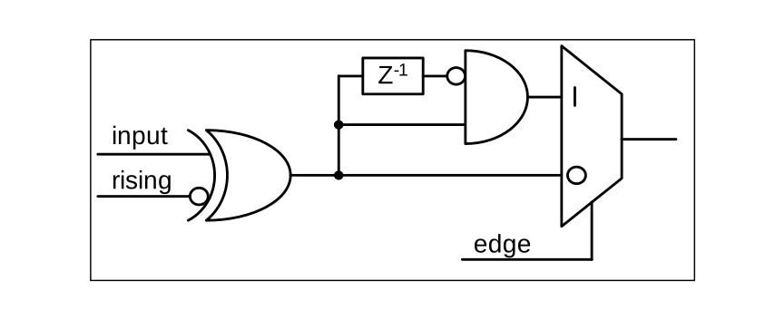
Figure 17 From the digital inputs Trigger, Gate, BUS0, BUS1, BUS2, and BUS3, a trigger unit creates an input flag for the trigger matrix.
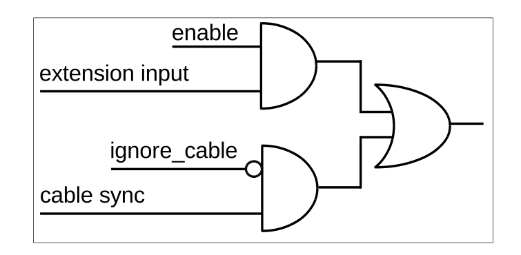
Figure 18 The extension block combines signals from the optional extension board and the sync cable.
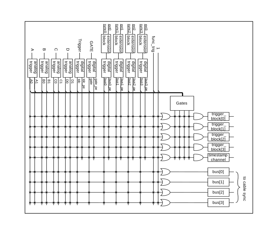
Figure 19 The trigger matrix combines triggers from all trigger units as inputs for the trigger blocks. The four gate units can be used to suppress the combined trigger.
Triggers can also be fed into the gating blocks. Gate blocks can be used to block writing data to the FIFO. That way, only zero suppressed data occurring when the selected gate is active is transmitted. This procedure reduces the PCIe bus load even further.