Gating Blocks
To decrease the amount of data transmitted to the PC, Ndigo5G includes 4 independent gate and delay units. A gate and delay unit creates a gate window starting at a specified time after a trigger, closing the window at gate stop. Both timing values — gate start and gate stop — must be set as multiples of 3.2 ns.
Trigger blocks can use the gate signal to suppress data acquisition: Only data that fulfills zero suppression specifications occurring in an active gate window is written to the PC.
As input, any trigger from the 4 trigger blocks, the GATE and Trigger inputs, a trigger from a connected board and the function generator can be used, as shown in Figure 20.
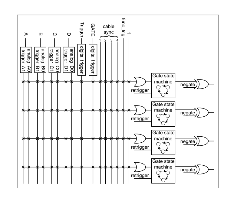
Figure 20 Gating Blocks: Each gating block can use an arbitrary combination of inputs to trigger its state machine. The outputs can be individually inverted and routed to the AND-gate feeding the trigger blocks.
The re-trigger feature will extent the gate if a trigger occurs during an active gate window. The gate signal can be inverted, causing an active gate to close for a time defined by the user.
Gating blocks are configured using ndigo_configuration::gating_block
Figure 21 shows the principle of the gate timing and delay unit.
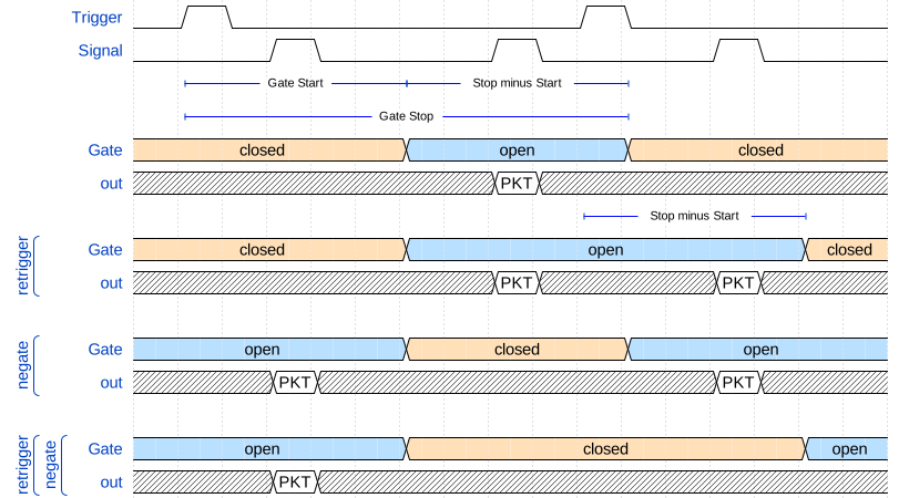
Figure 21 Principle of a gating block. Packets (PKT) are only recorded while the gate is open. Gate Start, Gate Stop, retrigger, and negate influence when that is the case.
Gating Example 1: Suppression of Noise After Starting an Acquisition
In mass spectrometer and other experiments, noise while starting data acquisition can result in undesired trigger events for that time period. To prevent noise in the output data, a gating block could be used to suppress all triggers during start-up.
The following example illustrates the use of a gating block to prevent noise:
The GATE input transmits a pulse on each acquisition start.
The trigger structure of the GATE input is used to select pulse polarity. Then, the GATE trigger is selected as gating block input and the gating block’s start parameter is set to 0.
The stop parameter is set to the desired length measured in 3.2 ns clock cycle and negate is set to true.
The gating block will now output a low pulse of the desired length whenever there is a pulse on the GATE input.
Enabling this gating block as an AND input to the trigger block, for which noise shall be suppressed.
Gating Example 2: Delayed Trigger
To sample a short window at a specified time after a trigger event on a channel, the gating block can be used to create a delayed trigger.
To do this, one of the triggers of the channel of interested is configured to the desired parameters by selecting the threshold, setting the edge polarity and enabling edge triggering.
Instead of directly using this trigger as input to the trigger block’s input matrix, the trigger is selected as an input to a gating block. The block is configured to start = delay (in 3.2 ns clock cycles) and stop = start*+1, as well as *negate = false. This causes the gating block to produce a one clock cycle pulse on its output after the specified delay.
To send this pulse to the trigger block, the gating block must be
enabled in the trigger block’s AND matrix and the
NDIGO_TRIGGER_SOURCE_ONE trigger source
must be selected.
Gating Example 3: Dual Level Trigger
The gates provide AND connections between each other (see the trigger matrix), which can be used for example in a dual level trigger.
For the acquisition of signal data with amplitudes between a lower and an upper bound, for example, two level triggers can be connected (Figure 22): a falling level trigger with an upper threshold and a rising level trigger with a lower threshold.
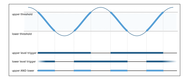
Figure 22 Measuring data with an amplitude between an upper and a lower threshold by means of a two-level trigger.
Since the triggers are only connected by OR in the trigger-block logic (see Figure 19 and Figure 23) they are assigned to one of the gates each and connected with AND via the gating block region of the trigger matrix. Because of the dead times of the gates it is important to enable the re-triggering feature. Furthermore, a precursor of 2 clock cycles is needed, because the gates are delayed in relation to the ADC samples.
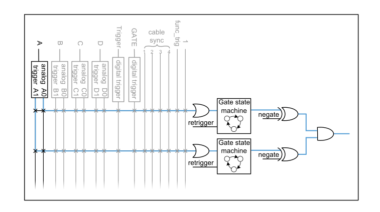
Figure 23 Gating block logic for the AND connection of two triggers.
Config settings can be found in the following code snippet.
config.trigger_block[0].enabled = 1;
config.trigger_block[0].precursor = 2;
config.trigger_block[0].length = 0;
config.trigger_block[0].sources = NDIGO_TRIGGER_SOURCE_ONE;
config.trigger_block[0].gates = NDIGO_TRIGGER_GATE_0 | NDIGO_TRIGGER_GATE_1;
config.gating_block[0].retrigger = 1;
config.gating_block[0].stop = 0;
config.gating_block[0].sources = NDIGO_TRIGGER_A0;
config.gating_block[1].retrigger = 1;
config.gating_block[1].stop = 0;
config.gating_block[1].sources = NDIGO_TRIGGER_A1;
config.trigger[NDIGO_TRIGGER_A0].rising = 0;
config.trigger[NDIGO_TRIGGER_A0].threshold = 10000;
config.trigger[NDIGO_TRIGGER_A1].rising = 1;
config.trigger[NDIGO_TRIGGER_A1].threshold = -10000;