Calibrating the TDC
After each update of the Ndigo5G-10 firmware the TDC has to be calibrated.
The calibration is done with the tool TDCCalibration.exe
which is available after installing the Ndigo device driver.
After invoking the application a window as shown in Figure Figure 29.
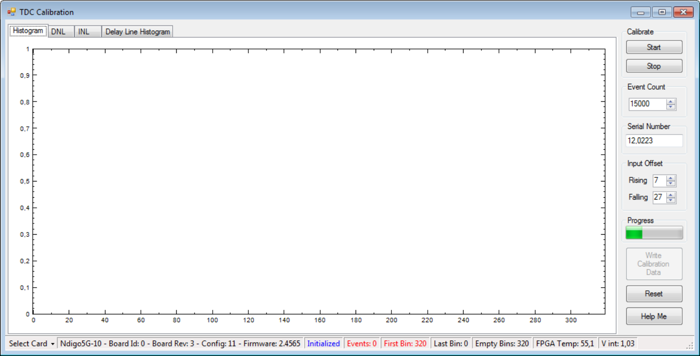
Figure 29 Screenshot of TDCCalibration.exe.
The calibration procedure is as follows:
Connect an external pulse signal to the Trigger input. The signal should be low active with a frequency in the kHz range. It must not be synchronized to the clock source of the Ndigo5G-10. The input frequency must not exceed 10 MHz. The pulse low and high width has to be at least 10ns each.
Set Serial Number according to the sticker on the card if the shown value is not correct.
Start capturing pulse events by pressing the Start button.
Adjust the Input Offset so that First Bin is in the range of 4 to 16. If First Bin is less than 4, increment Input Offset by one. If First Bin is greater than 16, decrement Input Offset by one. Repeat increment/decrement until First Bin is in the range of 4 to 16. Depending on the firmware revision the Input Offset value for a successful calibration may be in the range of 6–10 or 28–32.
When the Write Calibration Data button becomes enabled press it to update the calibration data on the card.
Calibration done!
The card can only be successfully calibrated if:
First Bin is in the range of 4 to 16
Empty Bins is less than (First Bin + 4)
at least 10,000 events have been captured
a valid serial number is set.
Hint
If the application reports an error, check if the input pulse is within specification.