Multi-Board Synchronization
Using several Ndigo devices in applications that use more channels than a single board can provide requires synchronized operation.
This way up to 8 Boards can be synchronized.
To ensure exact synchronization, a delay parameter needs to be set for each board.
This parameter might change in case boards are swapped, added, or removed and in some cases might change after a firmware update.
The calibration tool MultiboardCalibration.exe is available after
installing the Ndigo device driver.
It is used to find appropriate delay
values for each board in a given board setup.
After starting, the application lists all Ndigo boards found (Figure 24).
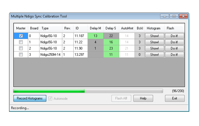
Figure 24 Screenshot of the MultiboardCalibration tool.
A board’s appropriate delay depends on whether it operates in master or slave mode. The respective values can be set in the column “Delay M” (for master boards) and “Delay S” (for slave boards).
The designated master board can be selected in the column “Master”. The calibration procedure creates a histogram for each board displaying the current delay between the boards.
The histogram can be viewed by clicking on “Show!”.
When the appropriate delay values are found they can be stored in the on-board flash PROM by clicking “Do it!” separately for each board.
Clicking “Flash All!” will write the values to all boards at once.
Note
Flashing the values might take up to 10 seconds during which the program might not respond.
Attention
If the application reports a “PLL not locked” error, check the cable.
If the recording of histograms does not make progress check the cable.
Make sure the cable is properly terminated at both ends and firmly attached to each card.
Calibration Procedure
Make sure the “Automode” is selected.
Record the calibration histograms by pressing “Record histograms”. The program will perform up to 200 measurements of the sync delay. After accumulating some data, the delay values found are reported in the column “AutoMmt”. The values can be verified by examining the histogram that was recorded. A board’s histogram should look like the one shown in Figure 25. During normal operation the delay will be adjusted such that the data points accumulated roughly coincide with the vertical markers in the upper panel. As the delay pattern is periodic valid delay values are between 0 and 31. Thus, the delay value found by the auto measurement should correspond to the distance between the vertical markers and accumulated data points. Hint: When moving the mouse pointer across the histogram the delay value of the current location is displayed.
After stopping the data acquisition, by pressing “Record Histograms” again or waiting for 200 measurements to complete, the delay values of the auto measurement need to be copied to the columns “Delay M” or “Delay S” depending on the corresponding board being a master or a slave. The correct field to copy the value to is highlighted in green.
You may record a new dataset as a crosscheck that the delay is now set to an appropriate value. By disabling “Automode” the new delay values are used. Press “Record Histograms” in order to start the data acquisition. After some time the histogram should look similar to the one in Figure 26.
The delay values for all boards in a set needs to be found. For the case a board acts as a master, the value “Delay M” needs to be adjusted, in case it is a slave, the “Delay S” parameter needs to be changed. In order to find the master-case delay values for all boards, the calibration procedure needs to be performed with every board acting as a master once. After changing the master board, the slave values of the other boards don’t need to be readjusted.
After finding all delay values, write the values to the on-board flash PROMs by pressing “Flash All!”.
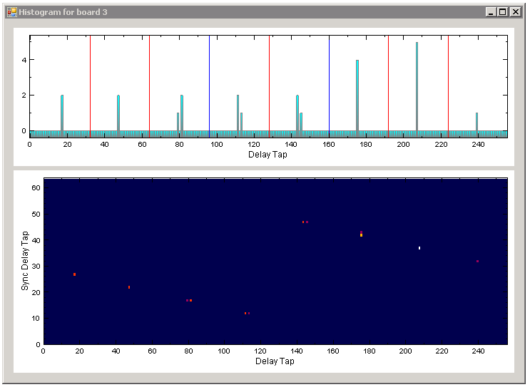
Figure 25 Histogram for the case the delay value for the board is not set correctly. Please note: the lower panel might differ from board to board, with the “step!” being at a different position.
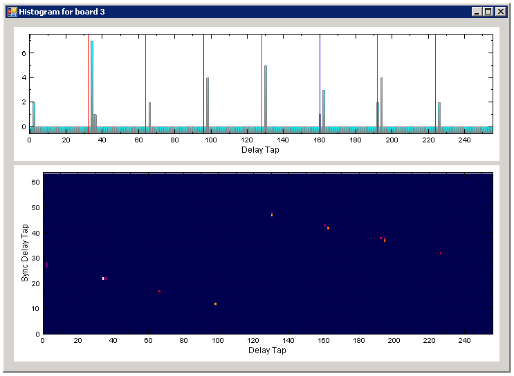
Figure 26 Histogram for the case the delay value for the board is set correctly. Please note: the lower panel might differ from board to board, with the “step!” being at a different position.
Synchronizing a Ndgio5G and an HPTDC8-PCI
In order to operate a Ndigo5G in sync with one or more HPTDC8-PCI boards, a board to board interconnection using a Ndigo Extension Board needs to be done.
The Ndigo Extension Board has four clock outputs. One of them needs to be connected to the external clock input of the HPTDC8 using a standard LEMO00 cable.
The Ndigo5G is connected to the Ndigo Extension Board using the Samtec ribbon cable provided with the Ndigo Extension Board.
The signals used for synchronization of the boards are transmitted by a standard 10-pin ribbon cable connecting the Ndigo Extension Board and the HPTDC.
A schematic of all necessary connections is shown in Figure 27.
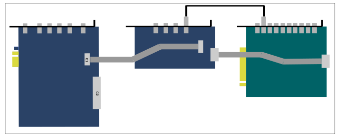
Figure 27 Ndigo5G (left) and HPTDC8-PCI (right) using an Ndigo Extension Board (middle).
In principle the user can use the standard device drivers of the Ndigo5G and the HPTDC8-PCI to perform data acquisition.
It is, however, recommended using the cronoSync library, which is a part of the cronoTools provided with the Ndigo5G device driver. cronoSync offers an easy group-based access to the data recorded and handles the synchronization of all cronologic data acquisition devices used.
A detailed description of cronoTools and cronoSync can be found in the cronoTools user guide.