Functionality
The xTDC4 is a “classic” common-start time-to-digital converter.
It records the time difference between a leading or trailing edge on the start input to the leading or trailing edges of the stop inputs (called timestamps).
Detection of rising and falling edges of the stop channels A–D can be enabled individually. Throughout this User Guide, transitions of the input signals are called hits.
The timestamps are quantized and are recorded in integer multiples of the data bin size of 5 ns / (3 × 128) ≈ 13.02083 ps.
The standard deviation of the timestamps is approximately 8 ps.
The maximum trigger rate on the start channel is 4 MHz.
Handling of Difficult Hits
To measure all hits with the maximum resolution the hits must fulfill all criteria set forth in this document. However, the xTDC4 does include mechanisms to provide as much information as possible for hits that fall out of these specs.
Problematic hits, as listed below, will be flagged in the output packets
(see Output Data Format, in particular crono_packet.data).
Short pulses
To reliably detect hits, the signal has to be stable for at least 900 ps before and after the edge that is to be measured.
However, pulses as short as 250 ps are usually detected at full resolution, but have a significant chance to be assigned to the wrong group or appear out of order.
For such hits bit 7
in the data word is set.
Close hits
Between multiple hits on a stop channel a dead time of approximately 5 ns is required for full resolution.
Hits that are closer together will only be reported with a resolution of
5 ns / 6 ≈ 833.3 ps. For these hits both
bits 6 and 7
are set.
High Hit-Rate
Data is copied from the 15-entry L0 FIFO to the larger downstream FIFOs at a rate of about 12 MHz per channel. If the L0 FIFO overflows, the high resolution measurement of some hits will be discarded.
In this case a measurement from an alternative TDC (referred to as Delay-Line TDC)
will be used that has a resolution of about 150 ps.
For these hits bit 6
in the data word will be set.
Grouping and Events
In typical applications, a start hit is followed by a multitude of stop hits.
The xTDC4 manages hits in groups (in some applications, a group of hits is often called an “event”).

Figure 5 Principle of the grouping functionality. Only the orange hits where the leading edge falls in-between start and stop are grouped, others discarded. Alternatively, trailing edges or both edges may be used to determine if a hit should be kept.
Figure 5 shows a corresponding timing diagram. For each Stop channel, you can define the range within which events are grouped. Hits outside that range are discarded.
Each Stop channel is configured by setting the
start and
stop values of the corresponding
channel[i].
If a second start hit is recorded within the range of a group, the current group is finished and a new group is started. Consecutive stop hits will be assigned to the new group (as long as they are within the group range).
The standard group range is 0 ≤ start ≤ stop ≤ 230–1.
If stop – start is larger than 224–1, the data will contain
rollover
(see XTDC4_HIT_FLAG_TIME_OVERFLOW
for details).
Start and stop are in units of xtdc4_param_info.binsize.
The maximum group range is 218.45 μs without rollover and 13.98 ms with rollover.
Attention
Hits on a Stop channel that are closer than 160 ns to the end of a group will not produce a high-resolution timestamp.
These hits will be flagged with the
XTDC4_HIT_FLAG_COARSE_TIMESTAMP flag.
This problem can be avoided by ensureing that the end of a group is at least 160 ns after the expected arrival time of Stop hits.
Auto-Triggering Function Generator
Some applications require internal periodic or random triggering. The xTDC4 auto trigger function generator provides this functionality.
The delay between two trigger pulses of this trigger generator is the sum of two components: A fixed value M and a pseudo-random value with a range given by the exponent N.
The period is
clock cycles with a duration of 4 ns per cycle.
M and N are configured with
xtdc4_configuration.auto_trigger_period and
xtdc4_configuration.auto_trigger_random_exponent,
respectively.
The trigger can be used as a source for the TiGer unit [see Timing Generators (TiGer)].
Attention
When using the Auto-Triggering Function Generator as a Start trigger while measuring asynchronous signals (relative to the Auto Trigger) on the Stop channels, a significant number of low-resolution Stops may be recorded (see Handling of Difficult Hits).
If such functionality is necessary, using the xHPTDC8 instead (which can produce a continuous stream of timestamps) alleviates this problem.
Timing Generators (TiGer)
Each digital LEMO-00 input can be used as an LVCMOS trigger output.
The TiGer functionality can be configured for each connector independently.
See xtdc4_tiger_block for a full description of all configuration
options.
Figure 6 shows how the TiGer blocks are connected. They can be triggered by an OR of an arbitrary combination of inputs, including the auto trigger. Each TiGer can drive its output to its corresponding LEMO connector. This turns the connector into an output.
The TiGer is DC coupled to the connector. Connected hardware must not drive any signals to connectors that are used as outputs, as doing so could damage both the xTDC4 and the external hardware. Pulses that are short enough for the AC-coupled inputs are available as input signals to the xTDC4. This can be used to measure exact time differences between the generated output signals and input signals on other channels.

Figure 6 Routing logic of the TiGer blocks. The LEMO inputs can trigger the TiGer blocks, which can enable outputs on the LEMO connectors.
Performing a Firmware Update
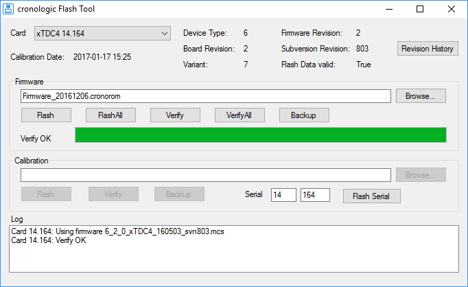
Figure 7 Screenshot of the XTDC4’s FirmwareGUI.
After installing the xTDC4 device driver, a firmware update tool is available.
By choosing FirmwareGUI.exe a firmware update can be performed
(the default location is under C:\Program Files\cronologic\TimeTagger4\apps\x64\).
After invoking the
application, a window as shown in Figure 7 will appear.
The tool can be used for updating the firmware and to create a backup of the on-board
calibration data of the xTDC4 unit.
If several boards are present, the one which is going to be used can be selected in the upper left corner of the window.
When pressing one of the Backup buttons, a backup of the firmware or the calibration data will be created, respectively.
In order to perform a firmware update, chose the .cronorom-file to be used by
pressing Browse.
The file contains the firmware data. By pressing Flash, the firmware is written
to the board.
Verify can be used to compare the firmware data stored on the xTDC4 to the one provided by a file.
Flash All and Verify All perform the corresponding operation on all boards which are installed.
Attention
The new firmware will only be used by the board after a power cycle, i.e. after switching the PC (or Ndigo crate) off and back on.
A simple reboot is not sufficient. Therefore, the information shown in the upper half of the application window does not change right after flashing a new firmware.
Note
After a firmware update, the xTDC4 must be re-calibrated in order for the Delay-Line TDC to work properly (see Handling of Difficult Hits).
Calibrating the Delay-Line TDC
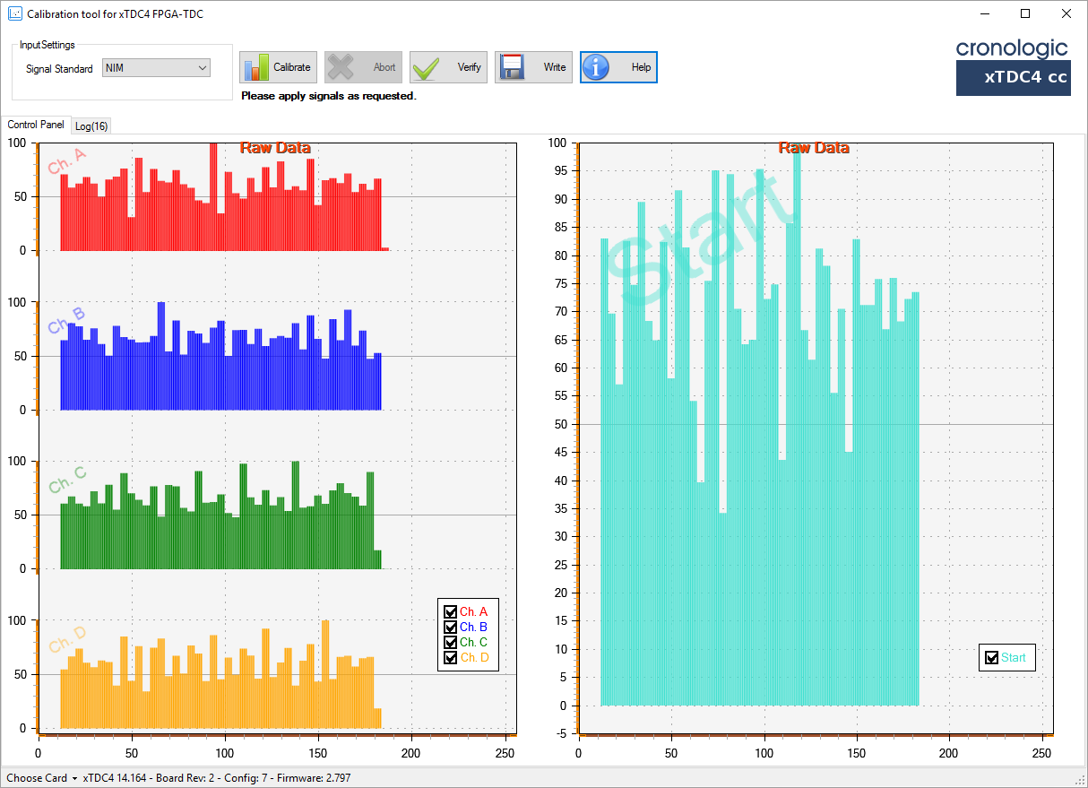
Figure 8 Screenshot of the XTDC4’s Calibration Tool.
After each update of the xTDC4 firmware, the Delay-Line TDC must be calibrated.
If you just performed a firmware update, make sure to power-cycle the xTDC4 before starting the calibration procedure.
The calibration is done with the tool XTDC4Calibration.exe (see Screenshot of the XTDC4’s Calibration Tool.) which is available after installing the xTDC4 device driver.
Connect an external pulse signal to the Start and Stop channel inputs. The signal must be low active. The pulse width must be between 10 ns and 200 ns. The pulse frequency must not exceed 1 MHz.
Use Calibrate to start the calibration procedure. Follow the on-screen instructions to gather calibration data on all channels. When all channels are calibrated use Write to permanently store the calibration data in the xTDC4’s on-board flash.