1 Hardware
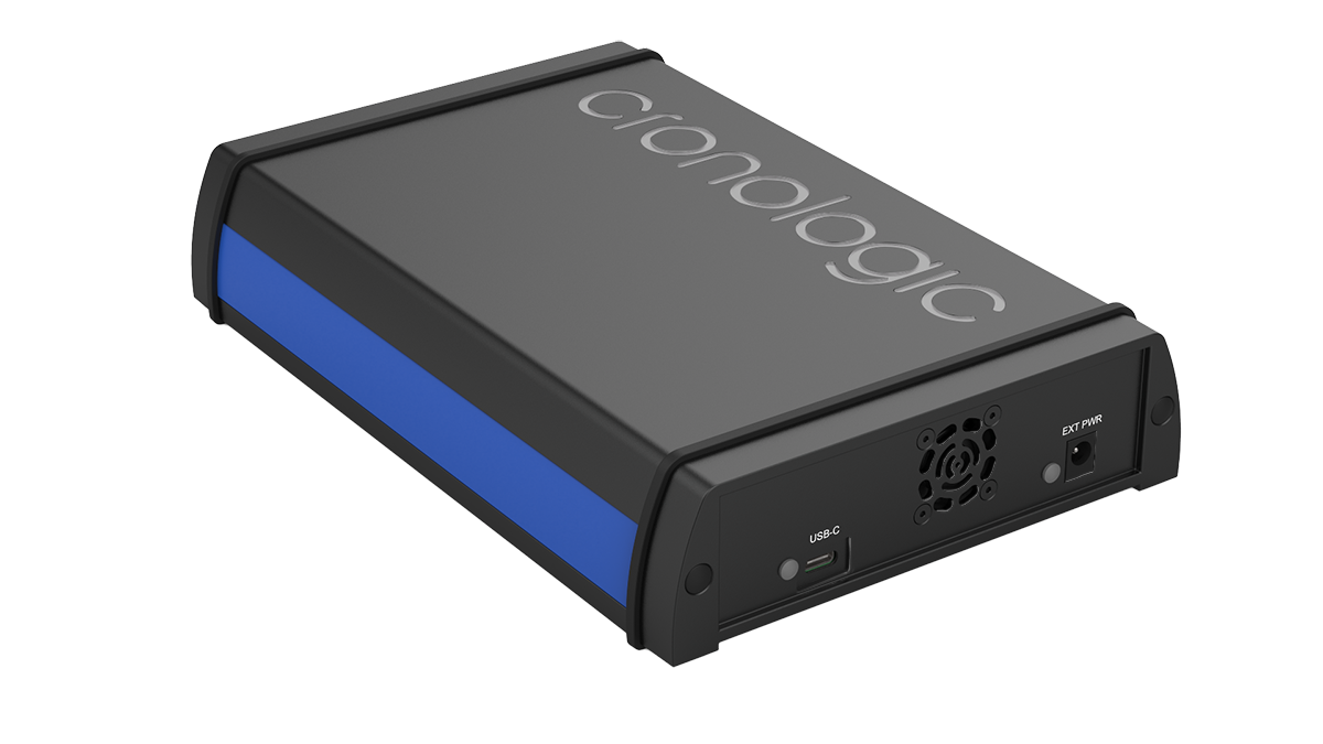
Figure 1.1: Overview of the TBT variants. The device is 240 × 155 × 50 mm big.
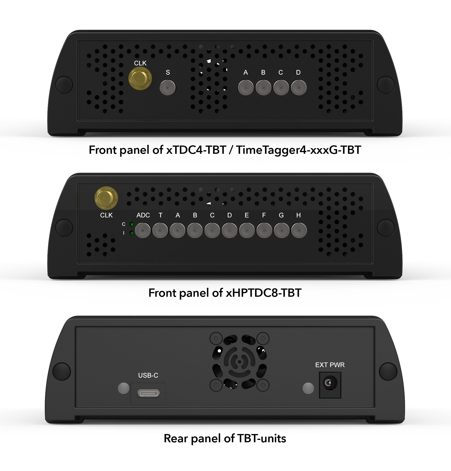
Figure 1.2: Front and back panel of the TBT variant of our TDC cards.
1.1 Power requirements
The power requirements and the need for an external power supply depend on the particular card.
- TimeTagger4 (all variants)
No external power supply is necessary. Power is supplied by the USB4 port.
- xTDC4
An external power supply providing 14–15 V DC @ 45 W is necessary.
- xHPTDC8
An external power supply providing 14–15 V DC @ 60 W is necessary.
If a power supply is necessary, we recommend the MeanWell GST60A15-P1J (15 V DC, 60 W, 4 A) power supply. However, any power supply providing sufficient power at 14–15 V DC with a plug as depicted in Fig. 1.3 is sufficient.
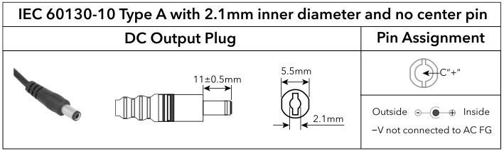
Figure 1.3: Requirements for plugs fitting the EXT PWR socket of the device.
Note
No external power supply is provided with the TBT variants of our TDC cards.
1.1.1 Power-up sequence
The below only applies to the xTDC4-TBT and xHPTDC8-TBT card.
For a proper boot sequence, it is important to:
First connect the power supply.
Then, the EXT PWR LED will light up green (unless the supplied power is not sufficient).
Only now establish the the USB4 connection.
Attention
The xTDC4-TBT and xHPTDC8-TBT cards will only work with the correct power-up sequence.
In case you did not follow the above procedure and the TBT card is not recognized by your device, remove the USB4 and power supply connections, then follow the correct procedure. If afterwards the TBT card is still not recognized, a reboot of your system is necessary.
Establishing the USB4 connection
Connect your device to any USB Thunderbolt port or USB4 port that supports PCIe using a proper USB-C cable.
The USB-C cable must support PCIe tunneling. This feature is typically available in:
USB4-compliant cables (with PCIe tunneling support)
Thunderbolt 3 or Thunderbolt 4 certified cables
Note
No USB-C cable is provided with the TBT variants of our TDC cards.
Attention
Many USB-C cables (including USB 3.x, USB 2.0, and dedicated charging cables) do not support PCIe tunneling and are not compatible with the device.
1.2 LEDs
The back panel features two LEDs:
- USB-C
This LED indicates a sufficient power supply by the USB-C port if green. It is only relevant for the TimeTagger4.
- EXT PWR
This LED indicates sufficient (green) or insufficient (red) power supply. If it is red, the connected power supply does not provide enough power. It is only relevant for the xTDC4 and xHPTDC8.
1.3 Inputs and connectors
For the front-panel connectors, refer to the main User Guide of the particular TDC card in your device.
1.4 Optional Addons
It is possible to buy wall brackets and tower feet for the crate ( see Fig. 1.4). These are not sold by cronologic, but you can purchase them from BOPLA enclosures.
- Wall brackets
- Tower feet
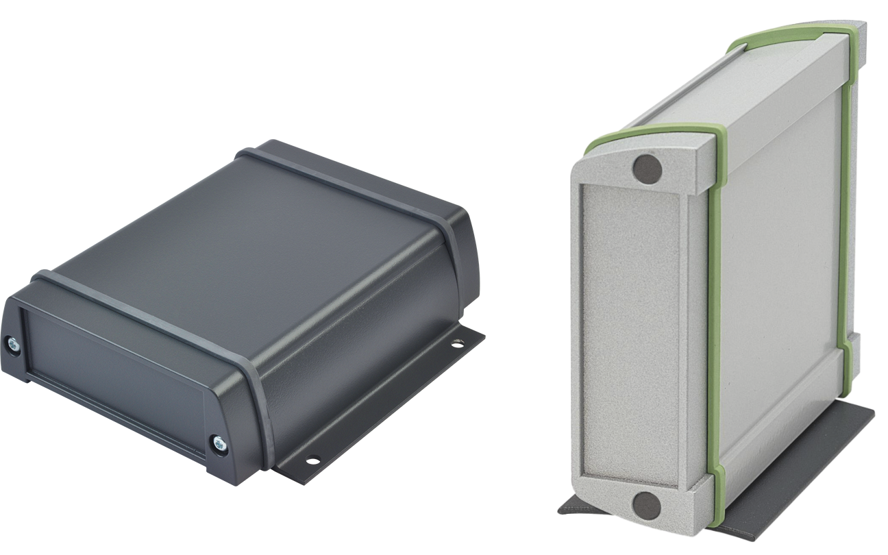
Figure 1.4: Optional addons for the TBT variant of our TDC cards. Left: universal wall brackets; right: tower feet (sold seperately by BOPLA enclosures).