Functionality
The TimeTagger4 is a “classic” common-start time-to-digital converter.
It records the time difference between a leading or trailing edge on the start input to the leading or trailing edges of the stop inputs (called timestamps).
Detection of rising and falling edges of the stop channels A–D can be enabled individually.
The time measurements are quantized. The quantization depends on the specific variant of the TimeTagger4, ranging from 100 to 1000 ps (see Table 1).
The timestamps are recorded in integer multiples of the data bin size (500 ps for Gen 1 and 100 ps for Gen 2).
Throughout this User Guide, transitions of the input signals are called hits.
To reliably detect hits, the signal has to be stable for more than one quantization interval before and after the edge.
Triggers on the Start channel must not occur less than 5 ns apart.
The TimeTagger4 records events without dead time at a readout rate of about 48 MHits/s for Gen 1 and 60 MHits/s for Gen 2. For Gen 2, the maximum readout rate of a single channel is 40 MHits/s.
Grouping and Events
In typical applications, a start hit is followed by a multitude of stop hits.
The TimeTagger4 manages hits in groups (in some applications, a group of hits is often called an “event”).

Figure 5 Principle of the grouping functionality. Only the orange hits where the leading edge falls in-between start and stop are grouped, others discarded. Alternatively, trailing edges or both edges may be used to determine if a hit should be kept.
Figure 5 shows a corresponding timing diagram. For each Stop channel, you can define the range within which events are grouped. Hits outside that range are discarded.
Each Stop channel is configured by setting the
start and
stop values of the corresponding
channel[i].
If a second start hit is recorded within the range of a group, the current group is finished and a new group is started. Consecutive stop hits will be assigned to the new group (as long as they are within the group range).
For Gen 1, the maximum group range is 0 ≤ start ≤ stop ≤ 231.
For Gen 2, the maximum group range is 0 ≤ start ≤ stop ≤ 232.
Start and stop are in units of timetagger4_param_info.binsize
(which is 500 ps for Gen 1 and 100 ps for Gen 2).
Ergo, the maximum group range is 1.073 s for Gen 1 and 0.429 s for Gen 2.
Note
For group ranges stop – start > 224, the timestamps
will contain rollover (see
TIMETAGGER4_HIT_FLAG_TIME_OVERFLOW.)
Auto-Triggering Function Generator
Some applications require internal periodic or random triggering. The TimeTagger4 auto trigger function generator provides this functionality.
The delay between two trigger pulses of this trigger generator is the sum of two components: A fixed value M and a pseudo-random value with a range given by the exponent N.
The period is
clock cycles with a duration of 4 ns per cycle for Gen 1 and 3.2 ns for Gen 2.
The standard values of M = 62500 and N = 0 result in a frequency of 4 kHz for TimeTagger4 Gen 1 and 5 kHz for Gen 2.
M and N are configured with
timetagger4_configuration.auto_trigger_period and
timetagger4_configuration.auto_trigger_random_exponent,
respectively.
The trigger can be used as a source for the TiGer unit [see Timing Generators (TiGer)], which enables internal triggering of the Start channel.
The trigger defines the period for the continuous mode (see Continuous Mode).
Continuous Mode
This feature is only available for TimeTagger4 Gen 2.
In continuous mode, the TimeTagger4 continuously records stop signals even without a start signal.
The data stream contains periodic packets with an absolute 64-bit timestamp, followed by a list of stop timestamps relative to the absolute one.
The frequency of absolute timestamps can be adjusted using the Auto-Triggering Function Generator.
Lower frequencies will create larger packets and have a larger latency for receiving packets. This potentially overflows the buffers.
Frequencies lower or equal to 600 Hz will contain rollover
(see TIMETAGGER4_HIT_FLAG_TIME_OVERFLOW).
Disregarding these points, the choice of frequency is arbitrary.
Attention
For continuous mode, timetagger4_channel.start and
timetagger4_channel.stop should be kept at their default values
(as provided by timetagger4_get_default_configuration()).
Configurable Input Delay
This feature is only available for TimeTagger4 Gen 2.
Each of the five input channels of the TimeTagger4 can be delayed for up to 204.6 ns with a 200 ps granularity.
Timing Generators (TiGer)
Each digital LEMO-00 input can be used as an LVCMOS trigger output.
The TiGer functionality can be configured for each connector independently.
See timetagger4_tiger_block for a full description of all configuration
options.
Figure 6 shows how the TiGer blocks are connected. They can be triggered by an OR of an arbitrary combination of inputs, including the auto trigger. Each TiGer can drive its output to its corresponding LEMO connector. This turns the connector into an output.
The TiGer is DC coupled to the connector. Connected hardware must not drive any signals to connectors that are used as outputs, as doing so could damage both the TimeTagger4 and the external hardware. Pulses that are short enough for the input AC coupling are available as input signals to the TimeTagger4. This can be used to measure exact time differences between the generated output signals and input signals on other channels.
When using one of the input channels as a source for the TiGer, the expected latency between signal input and TiGer output is roughly 95 ns.

Figure 6 Routing logic of the TiGer blocks. The LEMO inputs can trigger the TiGer blocks, which can enable outputs on the LEMO connectors.
Performing a Firmware Update
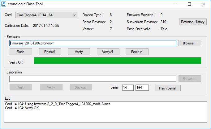
Figure 7 Screenshot of the TimeTagger4’s FirmwareGUI.
After installing the TimeTagger4 device driver, a firmware update tool is available.
By choosing FirmwareGUI.exe a firmware update can be performed
(the default location is under C:\Program Files\cronologic\TimeTagger4\apps\x64\)
After invoking the
application, a window as shown in Figure 7 will appear.
The tool can be used for updating the firmware and to create a backup of the on-board
calibration data of the TimeTagger4 unit.
If several boards are present, the one which is going to be used can be selected in the upper left corner of the window.
When pressing one of the Backup buttons, a backup of the firmware or the calibration data will be created, respectively.
In order to perform a firmware update, chose the .cronorom-file to be used by
pressing Browse.
The file contains the firmware data. By pressing Flash, the firmware is written
to the board.
Verify can be used to compare the firmware data stored on the TimeTagger4 to the one provided by a file.
Flash All and Verify All perform the corresponding operation on all boards which are installed.
Attention
The new firmware will only be used by the board after a power cycle, i.e. after switching the PC (or Ndigo crate) off and back on.
A simple reboot is not sufficient. Therefore, the information shown in the upper half of the application window does not change right after flashing a new firmware.
Note
After a firmware update, the TimeTagger4-10G (and only the 10G variant) must be re-calibrated.
Calibration of the 10G variant
After performing a firmware update, the TimeTagger-10G variant has to be re-calibrated. This does only apply to the 10G variant.
For this purpose, cronologic provides the timetagger4_10g_calibration command-line
tool The tool is located in the driver installation directory in apps\x64
(by default
C:\Program Files\cronologic\TimeTagger4\apps\x64\timetagger4_10g_calibration_64.exe
).
To perform a calibration, you need a NIM signal with a constant frequency larger than 20 kHz and smaller than 15 MHz. The stability of the frequency is crucial. A period stability of 6 ps has been verified to work.
Run timetagger4_10g_calibration_64.exe and follow the instructions on-screen,
that is:
Connect the NIM signal to the Start channel and press enter. The tool will calibrate the start channel.
After Start was successfully calibrated, connect the same NIM signal to channel A and press enter. The tool will calibrate channel A.
Repeat the last step for channels B, C, and D.
After a successful calibration of the TimeTagger4-10G, the message “Calibrated all channels successfully” will be displayed. You can close the calibration tool.
In case the calibration fails, please check the following:
The TimeTagger4-10G is installed properly (see Installing the PCIe Board).
A proper NIM signal with a constant frequency larger than 20 kHz and smaller than 10 MHz is used.
The NIM signal used conforms to the signal requirements laid out in TDC Inputs.
The NIM signal was connected to the appropriate input channel (see Figure 2).